Vandercook Upgrade Project

Universal I Vandercook Electrical Upgrade Package
It has been quite a few exciting years since my lovely wife Karen Sawyer introduced me to the fascinating world of letterpress and we jumped into the Bremerton letterpress community feet first. I decided to start this blog to share about the behind scenes life of maintaining our equipment, share solutions, share knowledge, and grow our community beyond the fun products my wife makes for her business. Two of my favorite pieces of equipment she owns is a risograph and a Vandercook Universal I. This is just another way I felt i can contribute to my wife's letterpress business dreams.
In general, the Vandercook is a remarkably reliable machine, so it is shockingly rare that components fail. That being said, when things do fail, the parts are becoming harder and harder to find. The letterpress cards my wife makes are fantastic, but a lot more goes on behind the scenes. Within the first month of starting work with our Vandercook my wife was printing a poster and mid operation the press stopped printing. Being an electrical guy, I jumped into action to repair our machine. When I opened the electrical panel, I was pleased to see a schematic was available even if it was disintegrating from age. The only hard copy I had was for a Universal III which contained this image, Figure 1, which is very close to the Universal I electrical design.

Figure 1 Vandercook Universal III Schematic
Clearly this diagram was drawn around the establishment of Y14 drawing standards and early IEEE/ANSI documentation standards.
My final goal is to create an upgrade kit that takes the obsolete and dated relays, contactors, rectifiers, resistors, and capacitors and modernizes everything WITHOUT the introduction of modern digital electronics. I want this kit to maintain the classical analog behavior of letterpress equipment. I have already had luck replacing relays in the past but now I am redrawing the schematic, parts lists, and a fully installable kit that will be much easier to repair in the future. The first challenge with all things is replacing the schematic. Stand by for future updates.
10/3/22
After a long day at the office, I returned to find my lovely bride printing away before resuming my Vandercook adventure. Her Meowdy sticker is by far one of my most favorite designs! If you have a friend or special someone who loves cats, this is a must.

That being said, back to the Vandercook fun. I started redrawing the schematic then decided I would actually make this more educational for anyone who may be interested in the mechanics behind their Vandercook Universals. The below image is going to improve every time I post to this blog.

Figure 2 Slightly Improved Vandercook Schematic
The Vandercook is a basic machine that uses standard 115 Volts Alternating Current (AC) to run a combination of relays, contactors, and timing circuits to make motors move forward and backwards, it really is that simple when you step back. The red solid line in Figure 2 indicates the path of positive AC movement while the dashed redline indicates where rectifiers have been used to create basic pulsed DC. I will use color to show the neutral path and inverse DC signals created in my following updates.
While I don't love paper and letterpress quite like my wife, the challenges her letterpress equipment brings is always interesting enough to maintain my interests. More to come tomorrow folks!
10/4/22
Day 3 is off to a slow start, work kept me late and my family always needs attention and support. It is still my mission to provide the best support I can to the Bremerton letterpress community and hopefully the world of letterpress through this Vandercook exploration.
Today I am going to talk some basic ac and power circuit of the Vandercook. Alternating Current is the basic power used in most American homes and commercial facilities and operates at a voltage of roughly 115 volts. In an AC system when a circuit is completed (flipping a switch on) the electrons are free to vibrate back and forth based on the power level, frequency and current available. Figure 3 shows a sine wave that usually represents the back and forth movement of electrons over time. While it may seem overly complex, it just represents the time it takes electrons to shift from side to side.

Figure 3 Sine Wave AC Example
This is incredibly important in decided what types of relays and contactors are needed for the future upgrade kit.
To best understand how the Vandercook letterpress uses this power I have broken down the major functions/topics to:
- Main Power Distribution
- DC Power Circuits and Uses
- Control Circuit
- Forward Circuit
- Reverse Circuit
- Time Delay Function
- Compound Motor Principles
- Electical Safety Grounding and Bonding
The immediate concept to grasp at power on is the switch is turned to the on position in Figure 4 below, it completes the circuit. This immediately causes the Ink Drum Motor to initialize and the lamp (identified as a NEON) to turn on. You will notice some of my symbols are changed from the initial drawing as I am trying to integrate modern symbols from the old letterpress schematic.

Figure 4 AC Input Basic Functions
Things that are important for building my future kit is that the motor and light are both 115V AC. it is also important to recognize my main On/Off switch is a Single Pole Double Throw (SPDT) switch. While I do not intend to put a light and a switch on the box, I will need a terminal board to interface with the wiring of these two objects.
I will show in following posts I will break down the sections of the press to show how the Control, Time Delay, Forward, Reverse, and DC power sections operate to drive the Vandercook. To my Bremerton letterpress community and future following - good night!
10/5/22
Today I am focusing strictly on the DC power circuits and their uses within the Vandercook. With my usual day here in Bremerton, letterpress is a bit of an afterthought until I get home. I work in a data analytics line of work during the day and supervise a team of great people but when I get home, I find that working on this project is pretty relaxing. So DC Power... The Vandercook, like many electronic devices has areas that depend on DC power or Direct Current. Unlike AC power, electrons do not move back and forth, they move in a linear path forward or backward (positive or negative directions). Figure 5 below is a snip from the Vandercook electrical schematic that shows what is called a bridge rectifier.

Figure 5 Bridge AC to DC for Shunt Field
A bridge rectifier is made from diodes and diodes themselves act like a door only allowing power to travel one way. A bridge rectifier converts AC power to DC power These handy devices use four diodes to prevent electrons from returning to where they just came from and generate what we call full wave rectification DC power. Figure 6 represents this change in electron transmission.
AC enters bridge then DC exits
Figure 6 AC to DC Signal Conversion
Based on the drawing, I am going to take some measurements, but it would appear that this means the motor is operating at both 76 Volts DC and -76 Volts DC to energize the motor and both the Shunt/Series fields inside the motor. I am not going to dive in deep on this topic yet. Suffice it to say, the motor is what we call a Compound DC motor and the fields in the image work within the motor for performance.
In Figure 7 below, you will see another snap shot of the Vandercook schematic. I have provided dashed blue and red lines on the outputs of the bridge rectifiers showing the path the DC sections of the schematic. Fuses are also placed at the inputs to each of the rectifiers for safety reasons. You will also see what is called a zener diode in the circuit which is used to maintain positive and negative DC voltages. I may discuss the zener diode in more depth later but for now, the most important thing to understand that this DC section is the most important part of your Vandercook electronics. The Forward and Reverse Contactors have significant roles here since they are essentially turning on either positive or negative 76 Volts DC. Positive DC power makes the motor spin one way, negative DC power makes it spin the other.

Figure 7 DC Voltage Circuits Identified
In Figure 7 above, two unique and more complex pieces of equipment crucial to DC performance of the Vandercook are the Break Adjust and the Speed Adjust. The Break Adjust symbol is an old symbol no longer used in modern electrical drawing for a device called a Rheostat. This device adjusts resistance to increase and decrease voltage which will adjust stopping and starting due to the electrolytic capacitor. The Speed Adjust symbol is also an old representation for what is called an Auto Transformer. This device is a variable transformer that is designed to change AC voltages. The purpose of these voltage changes causes the motor to spin continuously faster or slower based on the voltage into the bridge rectifier.
As i am considering the future kit that I am going to build and looking at Figure 7, It is important to note that I will need two traditional Bridge Rectifiers, 1 Zener Diode, Fuse Holders, Fuses, 2 Resistors, and 1 Capacitor. The1 Rheostat, and 1 Auto Transformer (sometimes called a Variac) are mounted to the machine and are physically adjusted by the letterpress operator (in my case my loving and awesome artist and wife Karen Sawyer). These tend to be a little more exotic parts so I plan to identify alternate new parts but they are not a priority to my planned upgrade kit just yet. They will also need to be tied to my terminal board though.
I am a little ahead today so I may write some more for any parties following out there. On behalf of the "behind the scenes wizard" of Pier Six Press, enjoy your day you wonderful Bremerton letterpress peoples! If you found this post helpful at all, please take a moment to look at my wife's products. She is a passionate artist with great taste in puns and gifty products.
11/6/22
Control Circuit Day. The purpose of the control circuit is to slow down and prepare the cylinder starting and stopping motions. For those of you from the Bremerton letterpress community reading this article, thank you! Today I am going to focus on the control circuit of the Vandercook. The Control Circuit is driven by the activation of two limit switches, 3LS and 4LS, which open and close the circuit to the Control Relay (ironically the control relay is a contactor and not an actual relay by definition). Figure 8 below is a snip of the drawing. I will talk about Vandercook limit switches further below. The small numbers scattered around represent wire numbers and I will use them to reference paths of current flow.

Figure 8 Control Relay and Limit Switches
When the press is first powered on the 2LS and 4LS limit switches are in the shut position. Figure 9 and 10 shows the limit switches in their initial starting position. With 4 LS pressed the Control Relay is prepared for activation by setting the press to run or pushing cycle on manual.

Figure 9 Limit Switches 2 and 4

Figure 10 Limit Switches 1 and 3
The limit switches change the direction of DC power to the motor depending on the position of the 4 at any given time. The Vandercook limit switches open and close the paths necessary to active the relays and contactors. When the control relay (contactor) is activated, it changes the positions of its contacts.
It is important aspect of our letterpress machine to understand contactors if we want to stick to making an upgrade kit. Contactors make the nice loud audible clicking noise that we are accustomed to hearing while printing bad ass stationery or posters. The main unique differences between relays and contactors are made for more power, they tend to have more safety features, and work at higher voltages. Contactors were heavily used in early arcades and pinball machines. Below I have included an image of a Contactor made by RBM that is in Vandercook control panel circled in red.

Figure 11 Vandercook RBM Contactor
When you look around the schematic you are going to see varieties of symbols that look like Figure 12 below. These symbols represent the starting position of a contactor and have labels next to them for which relay or contactor. To upgrade the contactors in this kit you need to understand the total number of Normally Open (NO) and Normally Closed (NC) connections.

Figure 12 Normal Contactor Positions When Not Activated
If you count contactor positions in the schematic in Figure 13 you will find there are a total of 2 NO and 1 NC identified to the Control Relay (CR) and the CR symbol itself represents the power input to activate it. Based on this detail I know the Control Relay has to be standard 120V AC power input with 2 NO and 1 NC. If you google search "Contactor 120V AC 2NO 1NC" you will find many potential supply resources. At this point I am not ready to make decisions on which ones to buy since a deep understanding of all relays and contactors in the Vandercook are needed before committing to a purchase.

Figure 13 Location of the Control Relay Default Positions
When the Vandercook input power flows across the control relay, it causes the positions of each CR to flip to opposite positions. This means that NC becomes NO and NO becomes NC. The location of the CR points on the picture are next to Speed Adjust autotransformer and a 200 Ohm resistor in between the DC power forward and reverse power inputs to the motor. As I was studying the Vandercook schematic I noticed that the circuit lacked proper grounding. I will definitely have to address this but I will tackle that at the end of the discussion on the schematic. In a nut shell, the Vandercook Control Relay activates forward and reverse circuits and also enables Speed Adjust output to the Bridge Rectifier reducing and increasing voltage.
Tomorrow I will get into the circuit specifically focused on forward and reverse circuits. Summarizing today, I need to evaluate my options for a 1 NC 2 NO 115V AC contactor, identify possible zener diode options, identify potential resistor sources, and identify bridge rectifier options. I hope some of my friends in the Bremerton letterpress community and our great pacific northwest community will find this useful. Good night everyone and more fun is to come.
10/8/22
So I am running a day behind and getting ready for sky diving today. Hopefully I can summarize my progress and provide everyone with an adequate update. Today I intend to focus on the Forward Circuit. Forward and Reverse are directly related to each other, and I will occasionally reference the Control Relay Circuit previously discussed. The meat and potatoes of a Vandercook Press is to roll fancy paper over a cool design to produce and reproduce that image. This is where all the magic happens in the circuitry of the Vandercook and it is quite impressive this old analog tech does what it does so well.
Going back to our initial Control Relay Circuit image you will notice the circles with F and R in them. These represent the activation circuits for the Forward and Reverse Contactors. We also previously discussed limit switches and you may remember from the images in Figures 9 and 10 that 3LS and 4LS are on opposite sides of the printing bed. This means that 3LS and 4LS cannot be pressed at the same time during operation. When our press is powered on, 4LS is in the closed position and 3LS is open. Figure 14 below is provided as a quick refresher.
Figure 14 Forward and Reverse Relay Schematic Locations
Looking at the bigger picture is a bit more complicated. Figure 15 shows all the relays and contactors in the schematic's activation points.

Figure 15 All Relays and Contactor Activation Points
In addition to our Forward and Reverse Contactors we also have both a Front and Rear Relay which you may notice correspond to our Limit Switches.
Both 4LS and 2LS are closed switches when we power on our Vandercook. Both 3LS and 1LS are open switches when we power on the Vandercook. These two starting points are crucial to understanding the circuit operation. Lets start with identifying the Forward Circuit relay and contactor positions:
4LS/2LS: Closed
3LS/1LS: Open
Forward Contactor (F) (3NO 1NC): 1NO on wires 2 and 6 is open and prevents the Forward contactor from receiving it's initial power. 2 NO positions close to the DC motor control power to A1 and A2. When closed, these allow + VDC to A1 and - VDC to A2 but as they are open no power can flow. The 1NC in the schematic is wired into the break adjust and effects stopping speed of the motor.
Rear Relay (RR) (2NC 1NO): The rear relay is energized at the initial power on of the Vandercook. This changes the marked 2NC 1NO to 2NO 1NC. These positions close the path of activation to the Reverse Contactor and enable the Time Delay Circuit discussed later.
Reverse Contactor (R) (2NO 1NC): The Reverse Contactor is not energized. Like the Forward Contactor, when activated it applies power to the DC Motor but reverse the power with - VDC on A1 and + VDC on A2. It also has a 1NC position that is currently Closed to the break adjust.
Front Relay (FR) (1NO 1NC): Possibly the simplest of the relays in the Vandercook, our Front relay has 1NO that is presently open preventing power flow to the Reverse, and 1NC that is closed allowing power to flow to the Forward contactor.
(UPDATED 6/4/2023) Time Delay Relay (TDR) (1NO 1NC NCTC): The TDR relay is a relay that uses a combination of the 150V 300 Microfarad (MFD) capacitor and resistors that control the delay speed of RUN mode. This relay is only activated in RUN mode. Normally Closed Timed Closed (NCTC) relays have a constant NC path, but when the relay is triggered it is only opened for a period of time before it resets. The NC path is represented with a special symbol.
See Figure 16 for highlighted reference points below
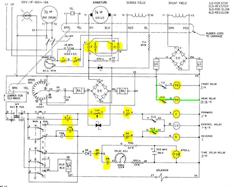
Figure 16 Reference NO NC Schematic Locations.
There are three options to start your Vandercook letterpress experience. Manual, Cycle, and Run.
CYCLE:
The cycle mode depends on the operator of the Vandercook to initiate the process by hitting the Cycle Start button. The is represented in the schematic by a push button just above the word CYCLE in Figure 16. When the TDR circuit activates this allows power to flow to the Forward contactor causing all NO and NC positions to invert. This allows the description of the Forward contactor above to turn on +VDC to A1 and -VDC to A2 spinning the DC motor in a specific direction.
As voltage is applied to the DC Motor it travels across the printing bed. As it travels initially 2LS opens and a second later LS4 opens. At this point all Limit Switches are open. As the cylinder travels across the printing bed, it next arrives and closes 3LS slowing down the motors rate of travel and a second later 1LS is closed. With 1LS closed, the cylinder now stops, and the conditions are met for the DC Drive Motor to reverse power and motion. See Figure 17 below.

Figure 17 Limit Switch Positions Over Time
Alright. Taking a pause from Vandercook Letterpress nerding to share a life event. I officially have 7 skydive jumps under my belt. A little about me: I love experiencing new things even when they are scary, I love everything electrical and science. I am a Veteran and spent 5 years of my life on submarines and also have over a year of service in the field in Afghanistan. Those wondering who wastes so much time writing about this letterpress stuff, my picture below having just finished another jump.

My buddy next to me is Georgi Babunadze from the country of Georgia. We served together in Afghanistan but he had never been pushed out of a perfectly good airplane before today. For anyone in the local Bremerton letterpress community seeking a new experience beyond the art of fancy paper, reach out and feel free to set a date.
Thats enough for today, more Vandercook status updates and education to come. You stay classy Bremerton.
10/10/22
So here we are again today exploring my wife's beautiful world of letterpress and my world of Vandercook glory. As always, I would be remiss to not ask you to check out my wife's products, she does amazing work with either letterpress or risograph (I plan to write a journal on writing drivers for Mac Risograph after this is over). A great surprise for someone who isn't expecting it, a great easy way to support my exploits is to buy a single (or more) of our hand poured candles. The labels of course are also made through letterpress on our Vandercook.
Right now I am building a table of existing parts and potential replacements. Contactors can range from $25 (cheap Chinese manufactured parts) to $200 western manufactured industrial grade Contactors. More than anything, I want the sound to be original to the old obsolete RBM contactors as possible and many Contactor manufacturers have focused on making Contactors more silent as well as faster and more reliable. Finding a model that still makes similar clicks and clacks is probably the hardest part. There is also a question of mounting, will this be a metal or plastic box insert, inversely I could create a kit that mounts to what is called a DIN rail. The advantage of a DIN rail is that it can be mounted to the existing internal chassis and it would be open to the air for both cooling and noise transmission.
I am leaning toward a DIN rail for the simplicity of mounting and almost every component can be mounted or connected to this. The DIN stands for Deutsches Institut für Normung (DIN) which was a German standard adopted by many companies back in the 1920s. There are numerous rail standards but the International Electromechanical Commission (IEC). IEC standards are pretty reliable and there are a wide range of manufacturers who make parts for these mounts. Example below in Figure 18 is linked to a great Wikipedia article on DIN rails.

Figure 18 Top Hat DIN Rail Example
For my list I need to put out a special thank you to Paul Moxon and the teams hard work at https://vandercookpress.info/. Their list of OEM parts saved my bacon and inspired me start this initial concept of an upgrade kit. Then I got sent to Afghanistan.... 4 years later I am finally getting to it...
The Table below is a work in progress and supporting data was derived from Power Carriage Parts - vandercookpress.info.
| Vandercook Kit | ||||||||||||
| Part | Old Mnfctr | Old Part Number | Part Type | Current | Schematic | V Input | Max Current Per Conn | V Out | Supply Source | Option A | Option B | Option C |
| Control Relay | RBM | RBM 45200-2 or RBM 45211-2? | Contactor | 3NO 1NC | 2NO 1NC | 115V AC | ||||||
| Forward | RBM | RBM 45200-2 or RBM 45211-2? | Contactor | 3NO 1NC | 115V AC | |||||||
| Reverse | RBM | RBM 45200-2 or RBM 45211-2? | Contactor | 3NO 1NC | 115V AC | |||||||
| Front Relay | Ohmite | DOSX-7T | Relay | 115V AC | 15A | |||||||
| Rear Relay | Ohmite | DOSX-7T | Relay | 115V AC | 15A | |||||||
| Time Delay Relay | Ohmite | DOSX-7T | Relay | 115V AC | 15A | |||||||
| Bridge Rectifier | Rectifier | 115V AC | ||||||||||
| Zener Diode | Diode | |||||||||||
| DIN Rail | Rail | N/A | N/A | Top-Hat | ||||||||
| Capacitor | Mallory | FP119A | Capacitor | N/A | ||||||||
| Fuses | Fusetron | FNM-5 | N/A | |||||||||
| Resistor 500 Ohm 25W | Ohmite | L25J500 | Resistor | N/A | ||||||||
| Resistor 200k Ohm 50W | Ohmite | L50J200K | Resistor | N/A | ||||||||
| Variac | Ohmite | VT 8X | Auto Transformer | |||||||||
Thats all for now folks. Bremerton letterpress community, you guys are the best. I am still missing comments so, while I know I am getting some visitors, please feel free to comment and help me feel that this has more importance than just my personal gratification of helping my wife (which is still the most important part). Karen Sawyer, I love you and you are an amazing artist and wife! To another day of Vandercook work tomorrow, good night everyone!
10/18/2022
So I have been a bit distracted from my Vandercook Universal letterpress project for a bit. My wife, Karen Sawyer, bless her heart has been dealing with a husband under a lot of pressure lately. I took Sunday to sit down and analyze our Vandercook and quickly realized it needed some serious servicing. My wife may be an amazing letterpress artist but sometimes her clean-up procedures lack the care of an engine mechanic. Spent quite a bit of time cleaning out old ink from the gears and regreasing neglected mechanical parts of our Vandercook. For the love of electrical theory and anyone in the Bremerton Letterpress community who may be curious about circuits my time has not been entirely idle. Below in Figure 19 i have a slightly animated gif file I created showing the initial AC power on sequence of the Vandercook Universal I. Figure 19 IS WRONG AT THIS PRESENT DATE. Correction to be made this week. This can also be found to be almost an identical electrical circuit for the Vandercook Universal III.

Figure 19 Vandercook Universal I Letterpress Power On Animation
Please reach out before using any of the animations I have produced here. I do love supporting the community but animated these things takes quite a bit of time even for the basic image above. Showing my continued frustrations with this process I should also note that Figure 19 IS WRONG AT THIS PRESENT DATE. Correction to be made this week. While this is relatively basic AC circuit to match the analog world of letterpress, i am frequently challenged with tracking the logic of this old diagram... Well that is enough time out of my day my fellow Bremerton and Kitsap letterpress community. Progress is progress no matter how small, I am again motivated to finish this unofficial course in Vandercook Universal I electrical.
6/2/2023
Hello wonderful letterpress community of Bremerton and the numerous people across the US who have reached out for contact and electrical advice. I am starting back up my efforts, life was happening and pulled me away from this activity for a time. I just finished a review of my previous work and realized I am still overdue for an update of my diagram. This is me checking in and letting everyone interested know that the fun is beginning to resume. More to come tomorrow hopefully.
6/4/2023
Alright Bremerton letterpress friends, a further update has been made to information on the TDR in the relay descriptions. I am not focusing much on the TDR circuit since most people I know usually use the CYCLE mode. In addition to updating the GIF which is almost done I have also started working a basic flow chart to help people isolate potential failures of electrical systems in their Vandercooks. If you are having issues with your Vandercook Universal model initially try to isolate the problem with these basic steps:
1. Flip Power On - Light should illuminate and inking motor should immediately start turning. Failure here indicates a burned out light, power cord issues, or a potential fuse.
2. Verify Your Mode - Does your failure occur RUN, MANUAL, CYCLE? If your press is failing in either RUN or CYCLE than shift to MANUAL and see if the problem occurs there.
3. RUN Failure Modes - Typically, if the failure is only occurring in RUN than the problem is within the Time Delay Relay circuit area itself. Common failures here will be the TDR itself, the capacitor, the diode, or the variable resistor behind the delay adjust. Run Vandercook in MANUAL to verify operation and if everything works the problem is in the TDR circuit.
3. CYCLE Failure Modes - CYCLE Mode Failures are typically going to be realized in the forward or reverse directions. Forward failures are most likely going to be cause by the RR relay, CR contactor, or F contactor but also can be caused by failures of the 2 LS and 4 LS Limit Switches. Reverse failures are most likely caused by the FR relay, CR contactor, or R contactor. Identifying forward or reverse is important to isolating which relays or limit switches are faulty.
More updates will be coming to help you all get back to printing that fancy paper! Until the next update, stay classy Bremerton letterpress community.